
Now you can simply chain a column of LEDs, with the control signal passed from LED to nearest neighbour.Įarly on in the video build log, you will note there are four power supply modules needed to feed this juice. These are based on the PD9823 controller, which can be programmed as if they were a WS2812, at least according to this analysis. This would be a nightmare to drive with plain RGB LEDs, even with cunning multiplexing, but luckily you can buy indexable LEDs in a through-hole package similar to the ubiquitous WS2812-based SMT LEDs you see around. A larger matrix like this 16 x 16 x 16 LED build, has a total of 4096. More LEDs need more power and increase control complexity considerably. It’s our pleasure to draw your attention to a lovely build, showing all the processes involved, the problems and the solutions found along the way.īuilding a small cube is somewhat of a trivial affair, especially without considering PWM colour mixing, however as simple maths will illustrate, as you increase the number of LEDs on each side, the total number will quickly get quite large. So just use a 3v battery between the two legs of the LED.LED cubes are really nothing new, many of us consider the building of a good sized one almost an electronics rite of passage that not so many manage to find the time or have the skill to pull off. I’m sure they would be pretty hard to replace. Your going to want to test you LED’s before you solder them into place because it would be sad if you put your cube together and had one in the middle that didn’t work. (this is determined by how long the leads are on your LED’s.

draw a grid to the size of the cube you want.

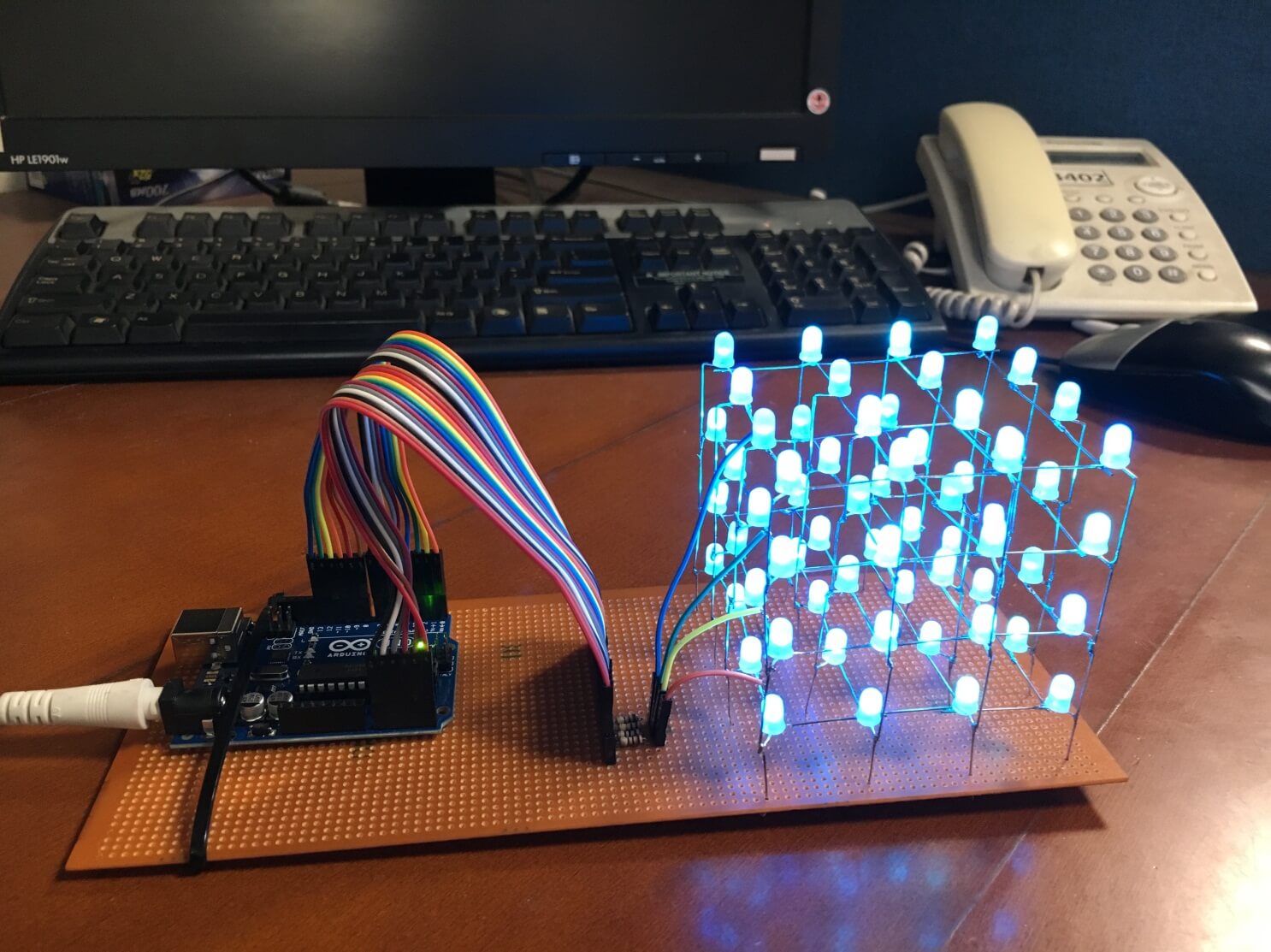
To begin the Construction of the cube use a drill with the proper size drill bit to make holes in a piece of wood. Now if I want to light up the LED in the upper left corner in the back (0,0,3), I just supply GND (-) to the upper layer, and VCC (+) to the column in the left corner. The cube is split into 4 layers of 16 LEDS.Īll the LEDs aligned in a vertical column share a common anode (+).Īll the LEDs on a horizontal layer share a common cathode (-). So that’s when I added the vertical columns of wire to solder the anodes too. After I started to do that I then realized that it would the be shorter than it is tall making it a rectangle rather than a cube. Therefore when Finally got the LED’s they were a lot smaller than I anticipated, and I did not want to redo my circuit board, so I just made frames out of craft wire to hook all the cathodes to. This is because I actually made all the wiring and circuitry when I was waiting for my LED’s to get here from China….(Note that it takes about two weeks for the lights to get to you). If you look at the pictures of mine the LED’s are not all just soldered to each other. The first thing you must do is make the cube. So if you already have a Arduino the cost is brought down to $40. The Arduino was the most expensive part at around $60 For MEGA and I think a UNO is around $30. In all the cost of this cube is relatively low at around $100 (according to where you get your parts) 1 Arduino (I went ahead and bought a MEGA so there’s room to expand for future projects, however UNO has just enough i/o ports).1-2 Perfboard (The kind with the little copper circles) (you only need one if you are good at compacting your soldering unlike me….).64 diffused LED Lights (it cost a lot less to order 1000 off ebay for around $20) (Also I used 3mm LEDs, but 5mm or 8mm would work to).Everything can be bought at your local Radio Shack It uses few components, so its relatively inexpensive.ģ. This cube is different from others for many reasons:Ģ. I decided to make the instructable after building it…so ill try to recreate the process the best I can.

So after reading everything I could find this is what I got.
ARDUINO LED CUBES PDF
Arduino Nano Projects List in PDF offline downloadable.
ARDUINO LED CUBES ANDROID


 0 kommentar(er)
